Published: August 2nd 2016
Conveyor belts transport tons of bulk material between disparate points, often at high speeds and over considerable distances. In most cases, electrical power is supplied only to the locations where it is needed, such as the drive motor, and is not typically available for general purpose use. Running auxiliary power can be both complicated and costly, requiring expensive labor and oversized cables to accommodate the inevitable voltage drop over long runs, as well as transformers, conduit, junction boxes and other components. Using even a small conventional generator to provide power introduces a different set of issues, including flammable fuels. In many operations, this lack of available power means that any monitoring of the conveyor must be done by technicians physically walking the length of the structure, which can be a difficult and time-consuming task when the systems are long and span difficult terrain.
A more efficient approach is to employ sensors to transmit important data from remote points to a central location where it can be monitored in real time and recorded for later analysis. But intelligent monitoring systems for any conveyor system require power for extended operation. Due to the distances involved, cabled communication systems are not ideal, and therefore wireless communication systems are more advantageous. Options such as solar are not well suited to the general conditions of a conveyor system, as monitoring devices are often required in an enclosed structure without access to sunlight, or for continuous operation during both day and night.
Kinetic Energy
A conveyor is driven by a multi-kilowatt motor, and this power is readily available system-wide in the form of the moving belt. The motors driving the belts are typically sized with a considerable power safety factor to account for parasitic loads, such as rolls with damaged bearings, tracking devices (which may not work continuously), sealing systems, belt cleaners and material changes due to different moisture levels and variable loads. For these reasons, engineers have searched for ways to take advantage of the available kinetic energy of the moving belt to bring power to the specific places where sensors and other devices would provide advantages.
One of the approaches to obtaining electrical power from the belt’s energy has been to use a wheel running along the belt surface that acts much like the small dynamo powering a bicycle light, spinning via contact with the belt surface. Unfortunately, conveyor systems are rarely a pristine environment, and in most operations some amount of bulk material leaves the belt in the form of dust and spillage, usually building up on both the rollers and the conveyor structure below the belt. This fugitive material rapidly adheres to the generator wheel, which causes a host of problems that can include vibration, excessive rolling inertia, high shaft loads and other issues which invariably cause the generator system to fail.
Another method that has been tried with some success is to build the generator into a roller itself, but load-carrying rollers are subjected to a wide range of stresses, including those introduced by fugitive material, heavy loads and high speeds. Sealing the generating mechanism and providing adequate support to prevent damage can be a daunting challenge, and any failure of the roller generally means the loss of the generator, which creates an expensive replacement proposition.
The Challenge
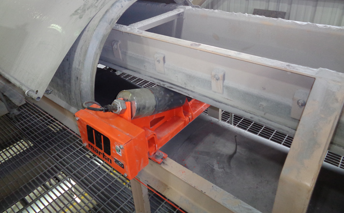
In most conveyor designs, the belt runs on a set of rollers that provide support and guide the belt. The typical conveyor roller is a very reliable device, with key components such as bearings, seals and the “steel can” all well understood in the industry. Martin Engineering product designers theorized that they could draw power from a moving belt by attaching an independent generator directly to one of the rollers. In this way, they felt that power could be drawn from the conveyor without altering the structure of the system or affecting its physical configuration.
Being able to add a generator to a roller delivers the benefit of utilizing the proven reliability of existing roller designs, while drawing power from the belt for a wide variety of electronic devices. If the attachment could be engineered with the versatility to retrofit existing idler designs, operators would not be required to maintain a special stock of conveyor rollers, as the generator could be employed on virtually any steel roller.
Product engineers developed a design to accomplish this through the use of a magnetic coupling that attaches to the end of an existing roller. The outside diameter of the generator matches the diameter of the roll, but places the generator outside the material path to avoid the heavy loads and fugitive material that tends to damage existing design attempts. The roll generator is held in a fixed position by the roll support system, but is not normally required to bear any of the material load.
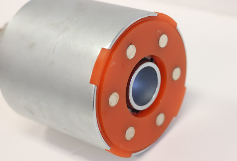
In the new, patent-pending design, a “drive dog” is attached to the end face of the roll that is resting on the generator, using magnets. The drive dog engages the generator through the outer housing’s machined drive tabs. The magnetic attachment ensures that electrical or mechanical overload does not force the roll to stop; instead the magnets will slip on the roll face.
Two seal flanges are attached to the shaft, preventing large debris from entering the generator. The seal flanges also house the secondary seal preventing infiltration of dust. Inboard of the seal flanges are bearing flanges, which support the rotating outer housing. Affixed to the housing’s inner diameter are a series of radially-arranged permanent magnets. When rotated by the drive dog attached to the roll, these generate electrical energy by induction in a set of windings around an armature. The wires from the armature exit the generator through a slot.
The conveyor roll loads are carried by the large support shaft in the generator, which does not rotate and is rigidly mounted to the idler support structure. The generator forms a lightweight driven unit that does not affect the existing roll in any way, except to be rotationally engaged via the magnets, and so draw a small amount of mechanical power in order to generate the electrical energy. The generator is sealed from fugitive material and forms an integral unit independent of the conveyor roll.
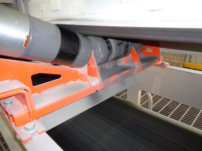
Because the outside of the generator has the same diameter as the outside of the roller, this allows the conveyor belt to ride over – and be supported by – the generator outer housing, in the event that the belt mistracks in this location. The bearings of the generator are able to handle the conveyor belt load, as they are of similar size to the roller.
On conveyors that already employ Martin® Trac-Mount™ Idlers (TMIs) outside of a loading zone, installation is as easy as removing the wing slide on one end and replacing it with the Martin® Roll Generator slide, a 2-minute procedure. The TMI design is particularly well-suited to tight spaces, with just 8 inches (203 mm) of clearance needed for 6-inch (152 mm) rolls. While standard rollers can be difficult to replace without ample clearance, the slide-in/slide-out roller frames allow quick service, without the need to raise the belt or remove adjacent idlers.
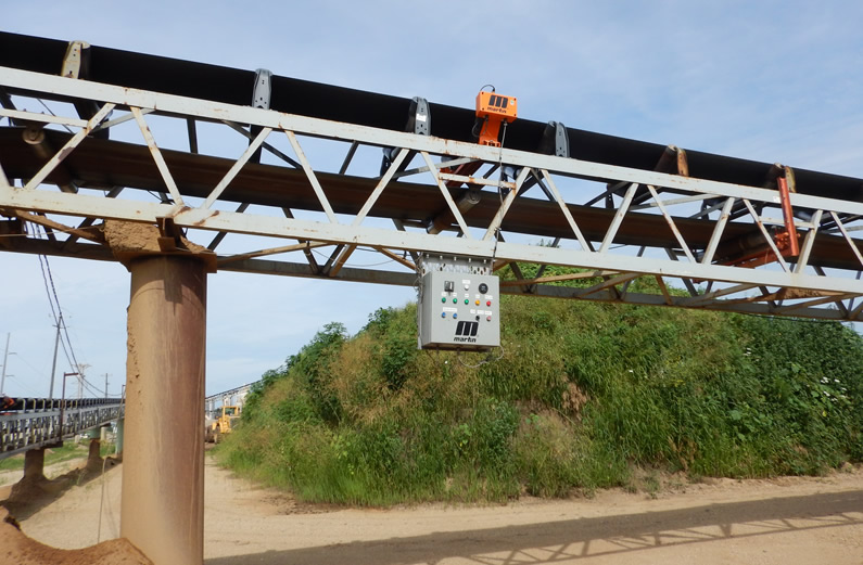
The generator can also be installed on its own mount or on other existing support structures, such as a belt tracker. All components to “condition” the power to a steady 24VDC are enclosed in a protective cabinet, typically mounted directly on the idler support slide.
The reliable power supply helps bring a new level of sophistication to conveyors, allowing designers to equip their systems with devices such as weigh scales, proximity switches, moisture sensors, pressure switches, solenoids and relays, as well as timers, lights and even additional safety mechanisms. Wireless communication can be used to transmit directly to a central controller, giving operators a cost-effective way to access data that has not been readily available in the past – and taking another step toward “smarter” conveyor systems.
Already in development is the capability to store power in a small battery bank, allowing the generator to produce 5-10x higher amperage for short periods to power higher-wattage devices.
We're Here to Help
Toll-Free 800-544-2947
Martin Engineering
One Martin Place
Neponset, IL 61345-9766
Get Directions
info@martin-eng.com
309-852-2384