Published: August 2nd 2016
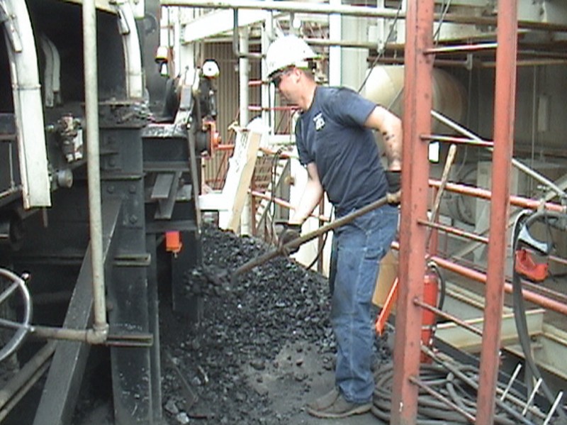
Transfer points can be problematic for any coal-handling operation. With loads of material rapidly dropping through receiving chutes onto a receiving conveyor with great force, material piles up around the frame and dust wanders throughout the area, collecting on idlers, pulleys and floors – affecting air quality. Workers are tasked with constantly cleaning up the material before it encapsulates the belt, subjecting them to the dangers of working around a moving conveyor, where even incidental contact can result in serious injury in a matter of seconds. Considering that many conveyor-related injuries occur during “routine” maintenance, managing fugitive material is a crucial element in the effort to reduce hazards and prevent injuries.
Coal operations need to only take a broad look at the expense that fugitive material has on a system to realize the full cost that comes with inefficient transfer point designs. Problems such as lack of proper belt support, poorly sealed chutes, damaged idlers and uneven cargo distribution can all result in spillage and belt mistracking, contributing to increased maintenance and cleanup costs and the potential for injury and compliance issues. These factors raise the cost of operation and lower profit margins.
A well-designed transfer point – equipped to handle intense belt speeds and production demands while producing minimal amounts of fugitive material – is a modern engineering achievement. Due to recently passed Mining Safety and Health Administration (MSHA) regulations, this modern technology may become an operating requirement. In a properly-engineered transfer point, each component, from the chute design to the cradles and dust seals, is employed to maximize its particular function and contain dust and fines, while at the same time providing easy access for maintenance. The entire system works more efficiently, retaining the maximum amount of payload while offering the safest work environment possible.
To remedy ongoing issues with transfer points, one needs to understand the key features of contemporary equipment designs. This article will walk through some of the fugitive material control mechanisms of modern transfer points, the problems they address and a short explanation on how they work.
Coal Transfer Points
Containment is the key to avoiding spillage and dust, and there are a number of components designed for this purpose. Although shaped transfer chutes and head boxes direct the material flow, most high-volume coal operations need one or more impact cradles to absorb the material stream’s force. Within the settling zone – located after the impact cradle in the conveyor chute box – slider cradles can then create a troughed belt to center the cargo and reduce disturbance, helping dust settle. By keeping a tight seal on the belt, apron seals can also be attached to the chute walls to prevent dust and fines from escaping.
For further containment, dust bags can be placed above the chute, utilizing positive pressure airflow to pull airborne particles out of the settling zone, while rubber curtains placed in the chute stop dust from escaping the skirted area. If the chute’s length, height and width are correctly configured to the speed and volume demands, the material will have a chance to settle prior to its exit. For more aggressive dust management, electrically-powered air cleaning systems can pull dust-filled air through a filter, exhausting clean air and collecting the particles in a hopper. In some cases, small solids can be directly added back into the material stream.
Airflow and Entrapment
With a constant stream of material falling on the receiving belt’s impact point, the transfer point can be incredibly unstable. By slowing the airflow in the skirted area, suspended dust is allowed to settle onto the material path. To contain the mixture of air and disrupted material, a stable, correctly supported belt is needed for the sealing components to rest against. Without a stable beltline, the belt will sag between idlers, and sealing components will not prevent air and fine material from escaping out of unsealed gaps, causing spillage and dust emissions.
A belt that is allowed to sag in the skirted area can also be prematurely and unnecessarily damaged. This is called “entrapment damage,” because when the belt sags between idlers, material can be brought back up into the next idler and become trapped in a pinch point. Friction caused by entrapment could not only damage the apron seal, but also gouge the belt, making it difficult for belt cleaning systems to perform correctly.
There are typically two acceptable ways to support a belt in the confined area of a transfer point. The first is to use steel or impacting idlers – or a combination of both – that are spaced close together. According to CEMA, idler spacing should be approximately 1 to 2 inches, however, to avoid problems associated with sag, consider designs with the least amount of spacing between idlers. The second way is to install adequate cradles with track mounted idlers in between for total belt support.
Impact
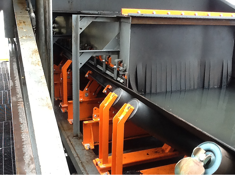
An effective, minimum-spillage transfer point requires that the belt’s line of travel be stabilized with proper belt support in the load zone. Located directly under the point where material is loaded onto the receiving belt, impact cradles come in different grades, depending on the size and weight characteristics of the cargo. The benefit of impacting idlers over standard steel idlers is the ability to absorb the shock of incoming loads to better protect the belt. Heavy duty impact cradles can be equipped with rubber or urethane impact bars with a top layer of slick UHMW plastic to minimize belt friction. Able to withstand impact forces as high as 17,000 lbf and drop heights of up to 50 feet, support beams in the center of the cradle are set slightly below the receiving belt’s line of travel. This way, the belt avoids sustained friction when running empty and yet can absorb harsh impacts during loading, while still retaining a tight belt seal. For high-volume operations, impact cradles should be classified as Heavy-Duty (H) per CEMA Standard 575-2000, fitting E-6 and E-7 conveyor configurations.
Steady Settling
Slider cradles, located down the length of the skirted area, have several functions. One is to create a trough angle that adequately centers the load. The trough angle also plays an important part in retaining a tight seal between the belt and the skirt. Utilizing track mount idlers in between each cradle will help create a smooth belt path through the settling area.
Some slider cradles are designed for conveyor systems with speeds up to 700 fpm. Each cradle may be 48 inches long with a single idler in between to avoid sagging. In the most effective designs, the belt glides over low-friction sidebars with an adjustable trough angle, allowing operators to achieve a precise fit to the apron seal.
Chute Sealing
A crucial requirement in any transfer point is an effective skirting and wear liner sealing system at the edge of the belt. Older systems may have wear liners that are fastened to the inside of the chute wall – often welded – which poses a significant risk to maintenance workers doing adjustments or replacements. The Occupational Safety & Health Administration (OSHA) considers most transfer chutes to be “permit-requiring confined spaces,” mandating that an “authorized entrant” perform the work inside the chute. An “attendant” must stand outside monitoring the safety of the person inside, while assisting in the removal of material from the chute. In some cases, a supervisor also administers this procedure. Since a grinder or torch is generally needed for this task, dust residue must be thoroughly washed from chute walls to avoid potential explosions. These maintenance requirements demand extended periods of downtime, negatively affecting productivity.
A more modern design features external skirting, which establishes the tight belt seal needed to eliminate fugitive dust and fines. After elevating the chute box above the material flow, an abrasion-resistant liner plate is mounted on the outside of the chute, followed by the skirting seal. Mounting brackets provide a tight hold, delivering precise adjustment of the wear liner to reduce spillage. This system closes the gap between the liner and seal, eliminating abrasion from trapped material without interfering with existing supports.
The external design requires minimal tools or confined space entry to inspect, adjust or replace wear liners or skirting, and in most cases can be performed by a single worker. The low profile of the skirting assembly needs only a few inches of clearance, allowing installation and maintenance in space-restricted areas. The design of these components drastically reduces scheduled downtime and the potential workplace hazards associated with replacement and adjustment.
Dust Filtration
Airborne dust is a common problem in coal-handling operations and is the frequent cause of regulatory fines. Conveyor design experts have found that the operation will be cleaner, safer and more productive when airborne particulates are controlled. In coal operations with limited space for a settling zone or especially dusty materials, dust bags and curtains may be essential components.
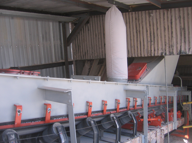
Dust bags prevent the escape of airborne particulates by venting the air and collecting dust at the same time. Installed above a hole cut midway along the conveyor loading zone and sealed with a grommet, the bag captures dust without the use of an energy-consuming fan or the need of a bag house. Instead, the unit uses the positive air pressure below to allow dust to escape the material flow and collect in the bag. Eliminating the air pressure by slowing or stopping the system causes the bag to empty dust back onto the conveyor, reuniting with the material flow.
Installed at the loading zone exit and mounted in the skirtboard cover, dust curtains can help create a plenum for dust suppression and dust collection. Typically made from thick rubber and cut to the belt width minus four inches, the recommended approach is a dual curtain configuration. A solid curtain is placed closest to the loading zone to contain dust from impact and settling material. The second curtain has slits that move individually with cargo as it passes, but retains a relatively consistent seal that follows the load profile to prevent dust from escaping. Additional curtains may be installed to reduce air movement and isolate dust.
If additional dust control is needed beyond these passive means, an air cleaner may be required. Most operators are familiar with central air cleaning systems, also known as bag houses. With this design, dust-laden air is pulled through ductwork to a central storage hopper or discharge point.
An alternative to the central collector is the integrated air cleaner system, which contains a suction blower, filtering elements and a filter cleaning system. Instead of a centrally located unit connected to dust generation points via ductwork, this type of cleaner is incorporated into the dust generation point itself. The particles are not extracted, but are instead collected within the enclosure and periodically discharged back into the material stream. Unlike central systems, the integrated approach employs a series of smaller, independently operating units, one at each dust generation point.
Operation Outlook
With a properly trained staff and thoughtfully designed components, transfer point maintenance is easier and safer than ever before. Thanks to new component designs and advanced engineering capabilities, the work environment has been drastically improved in recent years, and operators are reducing downtime due to cleanup and broken equipment caused by fugitive material and dust. These advances should motivate operators to make time for a cost/benefit analysis of new transfer point technology and assess the long-term benefits of increased efficiency and workplace safety.
Managers concerned with the overall safety and cost of operation need to go through the numbers to see how the impact of rising labor costs for cleanup and maintenance, combined with the expense of potential fines or forced downtime, can affect the bottom line. Using the technologies described here, even poorly-performing conveyors often don’t need to be replaced or rebuilt, but simply modified by experienced technicians installing modern equipment. These improvements will help operations increase efficiency, reduce risk and contribute to regulatory compliance.
We're Here to Help
Toll-Free 800-544-2947
Martin Engineering
One Martin Place
Neponset, IL 61345-9766
Get Directions
info@martin-eng.com
309-852-2384